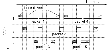
Figure 1: Packets segmented into flits or cells and interleaved on multiple VC's
Dept. of Computer Science, Univ. of Crete, and
Institute of Computer Science (ICS), FORTH,
Science and Technology Park of Crete,
P.O.Box 1385, Heraklion, Crete, GR 711 10 Greece
July 1998
© Copyright ICS-FORTH, Crete, Greece
[ Up to the Home Page of Wormhole IP over ATM at ICS-FORTH ]
ABSTRACT:
In the eighties, high throughput and low latency requirements
in multiprocessor interconnection networks
led to wormhole routing.
Today, the same techniques are applicable to routing
internet packets over ATM hardware at high speed.
Just like virtual channels in wormhole routing
carry packets segmented into flits,
a number of hardware-managed VC's in ATM
can carry IP packets segmented into cells according to AAL-5;
each VC is dedicated to one packet for the duration of that packet,
and is afterwards reassigned to another packet, in hardware.
This idea was introduced by Barnett
[Barn97]
and was named connectionless ATM.
We modify the Barnett proposal to make it applicable to
existing ATM equipment:
we propose a single-input, single-output
Wormhole IP Router,
that functions as a VP/VC translation filter between ATM subnetworks;
fast IP routing lookups can be as in
[GuLK98].
Based on actual internet traces, we show by simulation that
a few tens of hardware-managed VC's per outgoing VP
suffice for all but 0.01% or less of the packets.
We analyze the hardware cost of a wormhole IP routing filter,
and show that it can be built at low cost:
10 off-the-shelf chips will do for 622 Mb/s operation;
using pipelining, operation is feasible even at 10 Gb/s, today.
KEYWORDS: IP over ATM, connectionless ATM, wormhole routing, gigabit router, wormhole IP, routing filter.
Fast switching hardware, on the other hand, strongly favors small, fixed-size units of traffic, and fast routing decisions e.g. through small connection tables. Fixed-size units are preferred for a number of reasons. First, in general, they simplify hardware, thus reducing its cost and increasing its speed; it is precisely this effect that led RISC processors to adopt fixed-size instructions rather than the variable-size instructions found in earlier, CISC machines. Second, implementing multiple queues (e.g. per-class, per-output, per-flow) inside a shared buffer memory, in hardware, is almost impossible unless all memory allocation is done in multiples of a fixed-size block unit. Third, efficiently scheduling the traffic over a crossbar switch is almost impossible unless all traffic sources start and finish their transmissions in synchrony, thus implying that they all use a common-size unit of transmission. The fixed-size unit of traffic must be relatively small, so as to reduce delay for high-priority traffic. The upper bound on delay that can be guaranteed for high-class traffic is usually equal to a certain maximum number of low-class traffic units that high-class traffic may encounter in front of it, times the delay caused by each such unit; the smaller the size of the traffic units, the shorter this upper bound on delay becomes. [Additionally, small traffic units minimize the percentage of resources that remain unused due to fragmentation; of course, we do not want the traffic units to be too small, because that increases the header overhead and the switch controller rate or operation].
How can these hardware preferences be reconciled with the application requirements for variable-size packets and connectionless routing? Multiprocessor technology has already done that, in the eighties, using Wormhole Routing [DaSe87], [Bork90], [Gall97]. Figure 1 shows the basic idea of virtual-channel (multilane) wormhole routing [Dally92]. Variable-length packets are segmented into fixed-size flits (flow units); flit sizes have usually ranged from 4 to 16 bytes. A (modest) number of virtual channels (VC) is defined on each physical link. All flits of a given packet are transmitted on a single VC. Each flit has a header identifying the VC that the flit belongs to. Additionally, each flit identifies itself as a head, middle, or tail flit. A head flit is the first flit of a packet, and carries the packet's destination address; a tail flit terminates its packet and frees its virtual channel. Free virtual channels are reassigned to new packets. A wormhole router maintains a mapping table of incoming link-VC pairs onto outgoing link-VC pairs; this table is consulted for middle and tail flits, with tail flits deactivating their mapping entry. Head flits consult a routing table, in order for the proper outgoing link(s) to be determined; then, a free VC is sought on this (these) link(s), and a corresponding mapping entry is established.

Figure 1:
Packets segmented into flits or cells
and interleaved on multiple VC's
Asynchronous Transfer Mode (ATM) [LeBo92] is a networking technology that was developed in the last ten years with the intention of providing a common infrastructure for networks carrying all traffic types; there is considerable deployment of ATM hardware and software today, in local and wide area networks. ATM features the desirable hardware characteristics listed above: traffic is carried in fixed-size units called cells, and the cell size is reasonably small: 48 bytes of payload plus 5 bytes of header. Cell routing decisions are simplified by the presence of a connection table, indexed using a number of bits from the cell header. These index bits can be as many as 28, leading to large (and slow) tables; on the other hand, in many practical cases, it suffices to look at a lot fewer bits from the header (e.g. VP switching), thus leading to small and fast switches.
There are notable analogies between ATM and wormhole routing. In an ATM network, variable size packets are fragmented into cells before entering the network. Cells are transmitted over virtual circuits (VC) and virtual paths (VP), which are fixed routes over the network. All cells of a packet are assigned the same VC and are transmitted in order. This bears similarities to the operation of wormhole networks, as presented in figure 1: ATM cells are analogous to wormhole flits.
Connectionless ATM has been proposed by Barnett as a method for fast routing of IP packets over ATM hardware [Barn97]. Although Barnett does not mention wormhole routing, his proposal is essentially identical to adapting a wormhole router to operate on IP packets that have been segmented into ATM cells according to ATM Adaptation Layer 5 (AAL5). Because of this similarity, we propose and use the name Wormhole IP over ATM for what Barnett called Connectionless ATM. Wormhole routers, of course, also use backpressure (credit-based flow control), while ATM (usually) does not. The rest of this paper assumes conventional ATM technology, which does not use credit-based flow control, i.e. there is a difference in that respect from wormhole routing. Notice, however, that backpressure can be advantageously used with ATM too [KaSS97].
Wormhole IP over (connectionless) ATM is a hardware-only IP routing method, and hence differs fundamentally from the software methods that are in use today for routing IP over ATM --or for using ATM under IP [NeML98]. Software methods have a number of costs, overheads and associated delays that are not present in wormhole IP over ATM: (i) a very large number of VP/VC labels are consumed, or (ii) until a flow has been recognized, the first few packets in the flow are not switched; and (iii) new connections for new flows are established in software. These are further discussed in section 5.
This paper, first, modifies the Barnett proposal so as to make it practically realizable at low cost: instead of using modified ATM switches (CATM/ACS switches in [Barn97]), we propose to only build single-input, single-output wormhole IP routers, that function as VP/VC translation filters and interoperate with existing ATM switches and networks (section 2). Second, we simulate the operation of the proposed routing filter using actual internet traces, and we study its performance (packet loss probability when bufferless, else delay and buffer space) as a function of various parameters (number of VC's, network load, policing). The results are presented in section 3 and are very optimistic: a few tens of VC identifiers per outgoing VP suffice. Third, in section 4, we analyze the hardware structure of such a wormhole IP routing filter, and show that its cost is low, especially if it is made bufferless; operation at multi-gigabit per second rates is feasible, today.
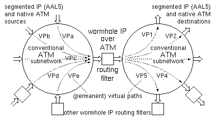
Figure 2: Wormhole IP router
as a filter between two conventional ATM subnetworks
The proposed wormhole IP over ATM router operates as a filter between two ATM subnetworks. This general formulation encompasses a number of interesting cases:
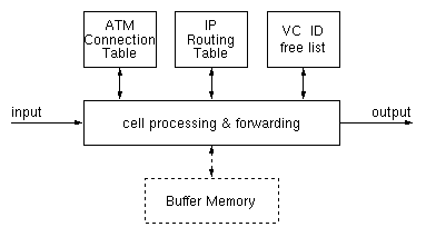
Figure 3: Functions in a wormhole IP routing filter
The IP Routing Table is the most challenging component of the filter --the other parts are relatively easier, as will be seen shortly. Fortunately, a lot of research was carried out recently on ways to speed up IP routing table look up [BCDP97], [WVTP97], [GuLK98]. The methods of [BCDP97] and [WVTP97] are rather software-oriented, while [GuLK98] is appropriate for hardware-only implementation. In this paper we use this latter method, whereby five 64 Mbit DRAM chips suffice for these IP route look-up's to be performed in a worst-case delay of two DRAM accesses each.
Figure 4 shows the ATM connection table in the routing filter of figure 3. The table is indexed using the VP and VC number of each incoming cell (less than the full 28 bits of these fields will suffice). For each such incoming VP/VC pair, the table lists a type (1 bit), a current state (2 bits), and an outgoing VP/VC pair (several bits, up to 28). The type bit differentiates the connections that have been set aside for native ATM traffic from those that the wormhole IP mechanism ``owns'' and uses. The VP/VC pairs of type ATM are owned and managed by the ATM network manager; they are used exactly like conventional connection identifiers, to label native-ATM connections. The wormhole IP hardware never uses these VP/VC pairs.
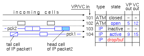
Figure 4: ATM connection table contents
The VP/VC identifiers of type IP are managed by the routing filter, in hardware. The ATM network manager considers that all IP-type VP/VC pairs correspond to legal, open ATM connections, that are unavailable for transporting other (native-ATM) traffic. As shown in figure 2, the ATM network switches these (IP-type) VP/VC pairs based on their VP value (VP switching) (the same can be done for the ATM-type pairs, but this is immaterial for the operation of the wormhole filter). [Of course, as far as the wormhole IP operation is concerned, any subfield of the 28-bit VP/VC field can be used as what we call ``VP'', and any other subfield can be used as ``VC'' --the choice is up to the ATM network manager]. While the ATM manager considers all IP-type VP/VC pairs as open ATM connections, the wormhole IP hardware differentiates them into active or inactive, using the state field of the connection table. An active VP/VC pair is one on which we have started receiving the cells of an IP packet, while not all cells of that packet have yet been received (packet 1 in figure 4). An inactive VP/VC pair (of type IP) is one on which all previously received IP packets have been received in full, and no new packet has arrived yet (packet 2 in figure 4).
The operation of the wormhole IP over ATM routing filter is described by the flow diagram of figure 5. For each incoming cell, the filter looks at its VP/VC number. One simple option (not the one shown in figure 4) is to distinguish ATM-type connections from IP-type ones based on the VP/VC field matching some particular bit pattern(s). Under this option, cells belonging to ATM-type connections are immediately and ``blindly'' forwarded to the output, without any processing. Figures 4 and 5 show the other option: the connection table contains entries for ATM-type VP/VC's, too. These entries (i) allow fine granularity in choosing the type of each VP/VC pair (minor point), and (ii) contain a translated VP/VC pair (major point), along with a validity bit (open/closed state). Under this option, shown in a dashed box in figure 5, the routing filter provides VP/VC translation for native-ATM traffic. This option may be useful for the following reasons. First, the routing filter already contains large (DRAM) memories, and the inclusion of a (quite) larger-than-necessary connection table may often incur only a small incremental cost. Second, relatively small ATM subnetworks can be configured to operate without any internal VP/VC translation; on the other hand, when joining together such subnetworks to form a large ATM network, VP/VC translation becomes necessary, and the translation table must now be large. As illustrated in figure 2, the proposed routing filter will often be positioned at precisely the locations where native-ATM prefers to have its (large) VP/VC translation tables; we then have the option of simplifying the ATM subnetworks, by not requiring them to perform any translation, while including such translation in the wormhole IP filters, where it will often come for only a small incremental cost.
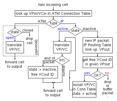
Figure 5: Flow diagram of filter actions per cell
When the incoming cell is of type IP, the state of its VP/VCin pair is examined. If the cell arrived on an active VC, it means that a (temporary, wormhole) connection has already been set up for the cells of the packet that it belongs to. The connection table specifies the VP/VC translation that has been established for these cells. After translation, if this is not the last cell of the packet, we merely forward it to the output and we are done with it. Remember that, under AAL5 segmentation, the last cell of a packet is marked using one of the bits in the Payload Type Indicator (PTI) field of the cell header. Now, if this PTI field of the cell indicates that this is the last cell of its IP packet, the temporary, wormhole connection that had been established for this packet has to be torn down; this is accomplished by marking its state as inactive in the connection table, and by returning the VPout/VCout identifier to the free list.
If the incoming cell arrived on an inactive VP/VC pair of type IP, then it is the first cell of an IP packet, since the connection became inactive either by initialization or by the tail cell of another IP packet (the effects of cell loss in the ATM subnetworks will be examined in section 2.2). The destination address of an IP packet that has been segmented according to AAL5, either without or with multiprotocol encapsulation, is fully contained in the first ATM cell of the segmented packet (this will also be true for IPv6). Taking advantage of this fact, the wormhole IP routing filter extracts this IP destination address from the cell that arrived on an inactive VP/VC pair. This address is looked up in the IP Routing Table (in hardware, as in [GuLK98]), thus specifying the desired outgoing VP; remember that choosing a VP corresponds to choosing a route in the ATM subnetwork (figure 2). Given a desired route (VPout), the next step is to find a VC identifier (ID) on that route for labeling the cells of this packet and differentiating them from those belonging to other packets, as explained in figure 1. This is done using the VC ID free list (figure 3), which may be a hardware-manipulated linked list or a bit mask and a priority encoder. If a free VCout is found, this VPout/VCout pair is written into the ATM connection table, at the entry corresponding to the VPin/VCin of the arriving cell, and the state of that entry is marked active. In this way, the current head cell of the IP packet effectively establishes a (temporary, wormhole) connection that will last until the tail cell of this IP packet is received. The head cell is then forwarded to the output, after undergoing the standard processing of active IP connections, i.e. VP/VC translation. Notice, however, that single-cell IP packets may exist, so the PTI field has to be checked, for head cells too; if PTI indicates an end-of-packet, then the newly established connection must be torn down right away (or it shouldn't be established to begin with). The Time-to-Live (TTL) field of the IP header is also contained in the head cell of the packet. If so desired, the routing filter can decrement this field (and drop the packet, as below, if the result is zero); this corresponds to each ATM subnetwork (figure 2) being counted as one hop in the path of the packet. Alternatively, if the entire ATM network is considered as a single hop, the TTL filed may be ignored.
If no free VCout exists for the desired VPout, the packet must be buffered until a VC ID is freed, when one of the other active packets that have been routed to the same VPout is fully received and forwarded. Alternatively, if such non-existence of a free VC ID is a rare event, we may simply drop the IP packet. The packet will also have to be dropped if the buffer is full (when there is no free VCout). In these cases, the state of this incoming connection must be marked as buffer or drop; in the case of buffering, a pointer to the proper buffer area must be inserted in the connection table, in lieu of VPout/VCout. The cost/performance tradeoff between buffering and dropping will be discussed in sections 3 and 4.
This concludes the general presentation on the operation of the wormhole IP over ATM routing filter. Next, we discuss some related issues: what happens with packets that arrive at the filter after one or more of their cells have been lost (dropped) in the ATM network; spreading of the packet's cells in time; quality of service and multicasting.
In connection with tail cell losses, we must also be careful concerning the following. If no next packet arrives over the VP/VCin of the lost cell for a long time, the outgoing VP/VC that was assigned to the previous packet is held in use (blocked) for a correspondingly long time. A time-out mechanism is thus needed to detect and release such long-held inactive outgoing VC's.
The above discussion concerned the wormhole IP filter as defined in figure 5. A number of enhancements are possible [HaSt98] in order to reduce the packet loss probability; given that this probability is already sufficiently low, however, these enhancements are not very appealing. First, the head cell of a segmented IP packet contains a packet length specifier. Based on this, the wormhole filter can compute the number of cells in the packet and initialize a counter in the connection table; each middle cell must decrement the counter. When the counter reaches zero, the incoming cell must be the end_of_packet; if the PTI field is not so marked, it means that the real tail cell was lost and this is the head cell of another packet. An artificial tail cell must then be generated for the previous packet (which is corrupted anyway), but the new cell can be handled intact, thus being saved from concatenation with the corrupted packet. Second, if LLC encapsulation is used before the the IP packet is segmented according to AAL5, then each head cell starts with the 8-byte sequence AA.AA.03.00.00.00.08.00 (hex). The routing filter can check for this sequence; if it not found, it means that the real head cell was lost, and this is in fact the second (or later) cell in the packet. In such a case, the entire (corrupted) packet can be dropped, thus saving the load of misrouted packets on the output network.
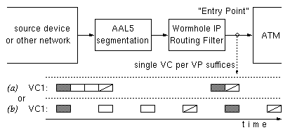
Figure 6: First entry point into ATM,
(a) without and (b) with policing
Other factors leading to the spreading of the cells in a packet are shown in figure 7. Both of these have to do with the multiplexing of traffic from several sources onto a single link. In figure 7(a), cells from two different packets arrive (possibly contiguously in time) simultaneously from two different inputs, and become interleaved as they are all placed in a shared FIFO queue. In figure 7(b), an outgoing link is fed from multiple queues; these may correspond to different priority levels, or to per-flow queues with (weighted) round-robin scheduling. Cells from the different queues are multiplexed on the outgoing link, hence the cells belonging to a single packet will no longer be contiguous in time, even if they were so before the multiplexing. For example, high-priority native-ATM cells may interrupt a train of IP-generated cells. This is precisely one of the reasons for carrying IP over ATM: the network is shared among multiple types of traffic, and some classes of traffic (e.g. high-priority native-ATM) enjoy low-delay guarantees because their cells can interrupt long packets of the other traffic type (IP).
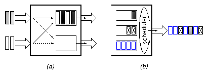
Figure 7: Factors leading to cell spreading
The inverse effect is also present: cells that have been spread apart in time can be brought back close to one another. As illustrated in figure 8(a), demultiplexing (departure of the dark cell in another direction) creates empty slots, while queueing behind other traffic squeezes out the empty slots and brings cells back next to each other.
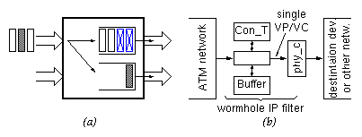
Figure 8:
Cell consolidation in network (a),
and packet reassembly at exit point (b)
Finally, at the ``exit points'' from the ATM network, IP packets must be reassembled from their ATM cells. A wormhole IP routing filter with buffer can accomplish that function too, as shown in figure 8(b). When a single VC identifier is available at the output of a routing filter, no packets can be interleaved on that output (or on that VPout), and hence packets are forced to depart sequentially. Of course, a wormhole IP filter that is configured in such a way will normally need to follow the buffering approach, rather than dropping cells when no available VCout is found (end of section 2.1). Notice that no IP routing table and no VC ID free list are needed in this filter configuration. [In some respect, this configuration is the complement of the one at ``entry points'' (figure 6); at entry points, no connection table and no buffer memory are needed].
First and foremost, wormhole IP allows the coexistence of (segmented) IP traffic with native ATM connections. One approach, for example, is to use separate VP's for the IP packets and for the native-ATM cells; the former VP's can be managed as ABR or UBR connections (e.g. lower priority), while VP's carrying native-ATM traffic can be of the VBR class, for example (higher priority). This allows one unified network, where those who need QoS guarantees can get them by using ATM, while IP traffic gets what it always used to have: a best effort service with no guarantees.
Rather than providing native-ATM traffic with an absolutely higher priority relative to IP packets, one may opt for (weighted) round-robin scheduling between the two kinds of VP's, or for plain FIFO scheduling without consideration for VP type. In such an environment, in order to be able to offer QoS guarantees to native-ATM connections, all traffic (including IP) must be policed. It is possible to perform such policing for the IP-carrying VP's in the wormhole routing filters; this will be discussed, along with simulation results, in section 3.4.
To differentiate the IP packets among themselves, in order to preferentially provide QoS to some IP flows, a method for IP flow classification is needed. Such classification capability can be added to the wormhole routing filters. In that case, the outgoing VP for an IP packet is selected based on both the routing table outcome and the flow classification outcome: multiple VP's are provided for each destination, each VP corresponding to a different service class in the ATM subnetworks. In fact, it suffices for flow classification to be performed at ``entry points'' only (figure 6), leading to the selection of the appropriate class of VP's for each IP packet. Downstream wormhole routing filters will choose the outgoing VP class based on the incoming VP class, and then the routing table will choose a specific VPout within the given VP class.
Multicasting becomes increasing important in modern networks. Efficient multicasting requires ``branching points'' (switches) in the network to have the capability to copy traffic onto multiple outgoing links; multicasting by generating multiple copies at a source and then forwarding all of them on the same link is inefficient. In an environment such as the one of figure 2, all branching points are in the ATM subnetworks. Thus, efficient multicasting can be supported using the ATM switches; supporting multicasting in the wormhole routing filters would be inefficient, since it would involve generating multiple copies of cells and forwarding them over the same (single) outgoing link. Multicasting for IP packets can be implemented by setting up special multicast VP's in the ATM subnetworks, and then inserting these into the IP routing tables of the wormhole filters.
To answer these questions, we simulated the operation of a wormhole routing filter like the one defined in section 2, under a traffic load that we generated based on real IP traffic. We simulated the routing filter operation over a time interval of 300,000 cell times. The input trace was generated as presented in section 3.1, based on real IP traffic at the FIXWEST West Coast federal interexchange node in January 1997 [NLANR97]. We preferred FIXWEST traces because they were taken from IP backbone routers, and are thus more representative of the overall IP traffic. Out of the information provided for each packet in the trace, we only needed and used the arrival timestamp, the IP destination address, and the packet length. The first few seconds of the trace sufficed for us to fill our simulated time of 300,000 cell times with IP traffic.
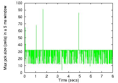
Figure 9: IP packet size
The larger the number of packets transmitted in a given time period, the more the VC identifiers that we are likely to need for them. The average number of packets per unit of time, obviously, depends on the throughput of the network link considered and its average load. To get an idea about the variance of the load, figure 10 plots the number of packet arrivals in each 5 ms time window for the 1600 such windows in the above trace (the window size is narrow enough to account for just a few tens of packet arrivals). We see that busy periods are about 3 times busier than average, and light-load periods are about 3 times less busy than average, i.e. a load fluctuation roughly in a range of 10:1.
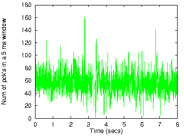
Figure 10: Traffic burstiness
Going from the original IP trace to a realistic pattern of cell arrivals for the wormhole routing filter under consideration is not easy. We assume that all the IP packets in the trace pass through the routing filter. We calculated the arrival time of the head cell of each packet from the arrival timestamp of that packet in the trace, by performing a linear scaling of the time axis. Four different scaling factors were chosen, in such a way as to yield average loads of 25%, 50%, 75%, and 85%, due to IP traffic, on the incoming link, over the 300,000 cell-time duration of the simulation input that we generated. On top of this IP load, we add a native-ATM traffic load of 2/3 of the remaining link capacity, i.e. 50%, 33%, 17%, and 10%, respectively. Thus, the total link load comes up to 75%, 83%, 92%, and 95%, in the four loading scenarios that we used. These are shown in figure 11.
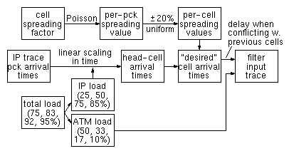
Figure 11: Input trace generation steps
Having specified the arrival time of each head cell, as above, we now need to find the times at which the other cells of the packets arrive at the routing filter. This, obviously, depends on the ATM subnetworks through which the IP traffic has passed, their topology, their load, their policing and scheduling schemes, as discussed in section 2.3. It would be very difficult for us to simulate such an ATM subnetwork, and the conditions of such a simulation would be questionable anyway. Instead, we use a parameter, which we call cell spreading factor, and, based on this, we generate an input trace, as outlined in figure 11 and described below. For each IP packet, we pick a random spreading value according to a Poisson distribution with average value equal to the spreading factor. To find the arrival times of the cells of a packet, we start by spacing these cells in time at a distance between each other equal to the spreading value chosen for the packet; then, we ``move'' each cell, in time, by a random number uniformly distributed between -20% and +20% of the spreading value of the packet. The rationale is the following: different packets have traveled through potentially different routes, so they each have a different spreading value; all cells of one packet, though, have traveled through a common route, in close time proximity, and have thus encountered similar traffic conditions, hence their inter-cell spreading is correlated. The final step is to find a specific cell-time slot where to place each cell of each packet, in the generated input traffic pattern. According to the head-cell arrival times specified by the scaled trace, and according to the randomized spreading process, the arrival times of cells from multiple packets may collide with each other, and may also collide with the arrival times of native-ATM cells. In such collision cases, the cell is placed in the next empty slot, after the native-ATM cells and the cells of previous IP packets have first been assigned to their slots in the time axis. [The current simulation results are from runs in which IP cells were placed before native-ATM cells; we are now in the process of making new simulation runs, with the placement order as listed in the text].
The most interesting number that characterizes the resulting input trace is the degree of interleaving: at each point in time, the degree of interleaving is the number of ``active'' packets, that is, packets for which the head cell was already received while the tail cell has not yet arrived. This coincides with the number of incoming IP-type VC's that are in the active or drop/buffer states (figure 4). The degree of interleaving is a useful figure because it gives an indication on the number of VC's required at the output. In fact, if the number of VC identifiers (for IP traffic) for each outgoing VP exceeds the maximum degree of interleaving, then all cells are guaranteed to depart immediately without ever needing to drop or buffer any cell. Of course, usually, quite less VC's per VPout suffice, since the active packets are distributed over multiple outgoing VP's.
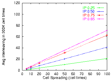
Figure 12: Average packet interleaving in incoming stream
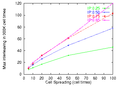
Figure 13: Maximum packet interleaving
Figure 12 plots the average degree of interleaving and figure 13 gives the maximum degree of interleaving over the 300,000 cell times of the generated input trace, as a function of the spreading factor, for the four different loads considered. As expected, interleaving is roughly proportional to the load and to the spreading factor. The values of spreading considered in our simulations is quite realistic, we believe. In lightly loaded ATM networks, factors like those considered in figure 7 should give spreading values in the range of 2 to 10. Under heavier load, or with per-VP policing, we expect higher spreading factors. A spreading of 100 is rather extreme: it corresponds to hundred-fold multiplexing (figure 7) without any intervening consolidation (figure 8(a)). Of course, for packets originating from very slow networks, the spreading factor will be large, so this must be taken into consideration in such environments; wormhole routing filters can be configured so as to reduce the spreading factor at their output, by providing buffer space and restricting the number of outgoing VC's per VP (section 3.3).
Another difficult decision in our simulations was the routing function to be used (the contents of the routing table). In a real situation, this is highly dependent on the topology and location in the internet. We decided to use a routing function that selects the same route for hosts with nearby IP addresses, while the routes for hosts with distant IP addresses are (pseudo-) uncorrelated. The routing function used is as follows: for a configuration with n outgoing VP's, route a packet destined to IP address d through VP number ((d div 57) mod n), where div is the integer quotient of the division, and mod is the integer remainder of the division; in other words, every 57 neighboring IP addresses are assumed to be in the same direction. The number 57 was chosen experimentally: it yields almost equal average load on all outgoing VP's.
The number of outgoing VP's is in general expected to be relatively high: it is approximately the number of ports of an ATM subnetwork. We want these subnetwork to be large, so that fewer routing filters are needed; on the other hand, the subnetworks cannot be too large, because then we run out of permanent VP's when connecting port pairs. We expect numbers between several tens and a few hundreds of outgoing VP's. Simulating a large number of VP's was hard, because the traffic on each of them became so sparse that our results were questionable. Thus, we restricted ourselves to at most 32 VPout; it is easy to extrapolate from our results to larger numbers of outgoing VP's.
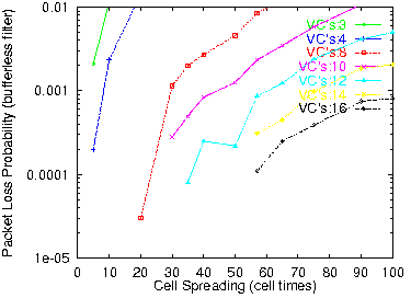
Figure 14: PLP for 75% IP load and 32 VP's
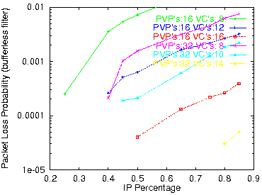
Figure 15: PLP versus IP load for spreading=50
In conclusion, a total number of VC identifiers for IP traffic on the order of a few thousand suffice for a bufferless routing filter to perform very well, with up to a few hundred outgoing VP's. These numbers are very realistic, and easily achievable with low-cost hardware (section 4.1). One would worry if packets dropped were preferentially long packets; if this were true, long packets would have a hard time passing through the filter, even after retransmission. However, this is not true: packets are dropped when all VC's have been exhausted by the packets ahead of themselves; thus, the decision to drop or not to drop depends entirely on the previous packets, and not at all on any property of the packet to be dropped.
Output scheduling, in each cell time, is as follows. If there is an incoming cell of native-ATM type, that cell is forwarded to the output. If there is an incoming cell of IP type and active state, that cell is forwarded to the output. Otherwise (i.e. when there is no incoming cell, or the incoming cell must be buffered), one of the previously buffered cells is forwarded; that cell is chosen as follows. A circular list of VP's that have buffered packet(s) and are ready, for transmission is maintained; a VP with buffered packet(s) is ready for transmission when a VC label has been assigned to the front packet in its queue of buffered packets. The buffered cell to be forwarded to the output is the front cell in the queue of the front packet of the next VPout in the circular list of ready VP's; after forwarding this cell, the pointer of the circular list is advanced to the next ready VP. [The current simulation results are from runs that followed a different scheduling algorithm: the pointer of the circular list is advanced to the next ready VP only after all cells of this packet have been forwarded; we are now in the process of making new simulation runs for the scheduling algorithm described in the text]. In this way, the filter interleaves buffered cells from all ready VP's, in a round-robin fashion; this is done in order to avoid bursts of cells of the same VP, i.e. in order to smooth the traffic injected into the ATM subnetwork. Within each ready VP, all buffered cells from one buffered packet (the front packet in the queue) are forwarded, before forwarding any buffered cell of any other buffered packet (even if more VC labels have become available in the meanwhile). This is done in order to reduce the degree of interleaving and the spreading factor on this outgoing VP. Notice that once there are buffered packets for a given VPout, all newly arriving packets destined for that VPout get buffered, and will then start departing in strict arrival order. When the last buffered cell of a buffered packet is forwarded to the output, if that was the tail cell of the packet, the packet is dequeued and its VC label is given to the next buffered packet for that VP. If this was not the tail cell of the packet, the packet is dequeued but its state is marked active in the connection table, so that further cells of this packet will cut-through to the output; the VC label is held by this packet; if another free VC label exists for that VPout, that label is given to the next buffered packet for this VPout.
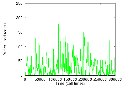
Figure 16: 32 VPs × 2 VCs each; 75% IP load; spreading=20
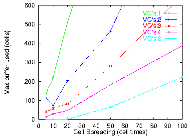
Figure 17: 32 VPs, 75% IP load
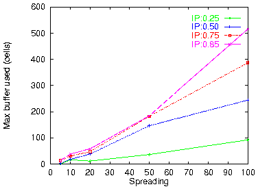
Figure 18: 32 VPs × 4 VCs each
For a routing filter that buffers cells in the absence of outgoing VC labels, the first question concerns the amount of buffer space needed. Figure 16 plots buffer occupancy as a function of time for some representative traffic parameters but with just 2 VC's per VP. Even with so few VC identifiers available, a buffer space of just 200 cells (11 KByte) suffices. Figure 17 gives the maximum buffer occupancy for various spreading factors and number of VC's per VPout. Figure 18 does the same for various IP traffic loads. We see that a few tens of Kilobytes of buffer space suffice even when there are as few as 4 VC labels per outgoing VP.
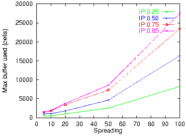
Figure 19: Reassembly buffer space: 1 VPout, 1 VCout
A special case of interest is IP packet reassembly at an exit point from the ATM network (figure 8(b)). The routing filter will automatically perform packet reassembly when configured with a single outgoing VP/VC pair. Figure 19 plots the buffer space needed in this case for various spreading factors and IP traffic loads. We see that quite larger buffers are needed now: several thousands of cells (hundreds of Kilobytes) are needed for spreading factors up to 50, while spreadings of 100 require one or a few Megabytes of buffer space for packet reassembly.
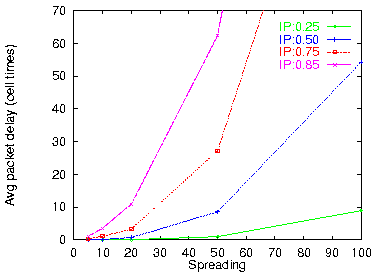
Figure 20: Average delay (32 VPs × 4 VCs each)
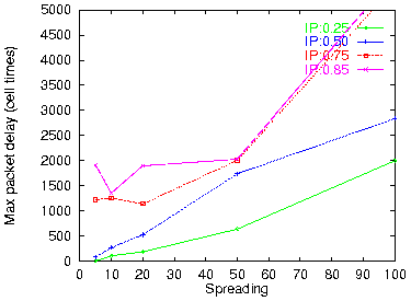
Figure 21: Worst case delay (32 VP × 4 VC)
The other performance metric of interest, for a routing filter that can buffer cells, is the delay caused by such buffering. Considering that a packet transmission is complete when its tail cell has been transmitted, we measured the delay of each packet as the time elapsed between its tail cell arrival at the filter and the departure time of that tail cell from the filter. Figure 20 plots the average packet delay, and figure 21 plots the maximum (worst case) delay seen during the 300,000 simulated cell times. We observe that the worst-case delay is about two orders of magnitude worse than the average packet delay. This is important: it tells us that, when there are insufficient VC labels, most packets suffer very little, but some packet suffer a lot, thus making QoS quite unpredictable.
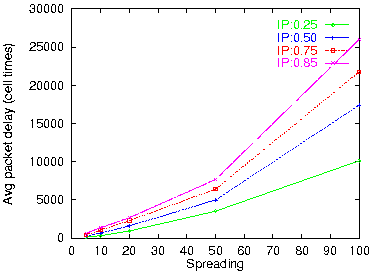
Figure 22: Average reassembly delay (1 VPout, 1 VCout)
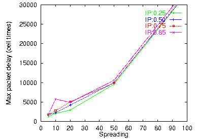
Figure 23: Maximum reassembly delay
Finally, figures 22 and 23 plot the delay incurred by packet reassembly, at an exit point with 1 VP and 1 VC. We see that in the case of reassembly both the average and the maximum delay are large; the worst-case delay is only about twice longer than the average. The delays encountered are in the thousands or tens of thousands of cell times (milliseconds, for 622 Mbps links); only for very small spreading values do we see delays in the 0.1 to 0.5 ms range. It is important to realize that wormhole IP over ATM saves us from precisely these reassembly delays at every IP router encountered on the path of a packet!
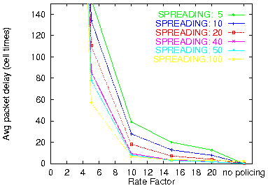
Figure 24: Leaky bucket with burst=1
(50% IP load, 32 VPs × 8 VCs)

Figure 25: Burst=5
Figure 24 shows the average packet delay, with policing and various rate factors, and without policing; the burst size is 1 (no burstiness allowed). Figure 25 shows the same numbers when bursts of 5 cells are allowed by the leaky buckets. A rate factor of 10 corresponds to a rate of (50%/32)×10 ~= 16% for each (per-VP) leaky bucket. For such a policing rate, we see that the average packet delay does not exceed 40 cell times, and goes down to 25 when a burstiness of 5 is allowed. For spreading values of 40 or more (incoming traffic), the average packet delay is less than 10 cell times (larger spreadings roughly correspond to stricter policing upstream in the network). For this same rate factor of 10, the maximum packet delay seen during the simulation (not shown here) ranged from 500 (large spreadings) to 1000 (small spreadings). For a rate factor of 5, corresponding to a limit of 8% of the outgoing link capacity per VP, the average packet delay was on the order of 100 cell times, while the worst case delay ranged around 4,000 cell times. The total buffer space needed (not shown in the figures), for the basic routing filter as well as for the policing queues, is less than 200 cells for a rate factor of 10, and grows to 400 cells for a rate factor of 5, and further to 1,000 cells when the rate factor drops to 3.
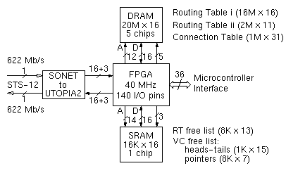
Figure 26:
Block diagram of 622 Mbps bufferless wormhole routing filter
In this example design we allow up to 1024 outgoing VP's, and up to 8K VC labels for IP traffic in all of the outgoing VP's. Thus, one can have configurations with 1K outgoing VP's × 8 VC's per VP, or 512 VP's × 16 VC's, or 256 VP's × 32 VC's, and so on; as we saw in section 3.2, these yield excellent performance. With these sizes in mind, the connection table contains 13 bits of outgoing VP/VC (for IP connections), and we need up to 1024 free lists of VC identifiers (one per VP), and up to 8K free VC ID entries. The latter two are included in an SRAM chip (figure 26), together with the free list for the second stage of the routing table [GuLK98]. Cell processing, header translation, and forwarding are performed by a field programmable gate array (FPGA) chip. The FPGA connects to the DRAM and SRAM chips, and to a SONET/UTOPIA-2 conversion chip; a microcontroller may also have to be included in the routing filter, if it turns out to be too complicated for the FPGA to maintain the Routing and Connection Tables by itself, according to instructions that it receives through the ATM link. These connections amount to using, e.g., a 208-pin FPGA (like the Altera EPF10K40-RC208), with at least 140 user I/O pins.
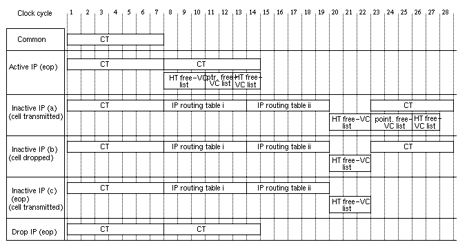
Figure 27: Memory access timing
for the bufferless wormhole routing filter
Timewise, we need 28 clock cycles for the worst case operation (open new IP connection) that has to fit inside a single cell-time. The corresponding timing diagrams are given in figure 27. Since the cell time is approximately 700 ns for 622 Mb/s, the clock period can be as long as 25 ns, requiring a clock frequency of 40 MHz or higher. We have assumed that a DRAM access takes 6 clock cycles (150 ns); reading two consecutive words from the connection table is assumed to take 7 cycles. SRAM access can, in principle, be performed in 1 clock cycle, but we conservatively allowed 3 cycles per SRAM read and 2 cycles per SRAM write, in order to account for the long FPGA setup and output delays and the consequent need to use pipeline registers at the FPGA-SRAM interfaces.
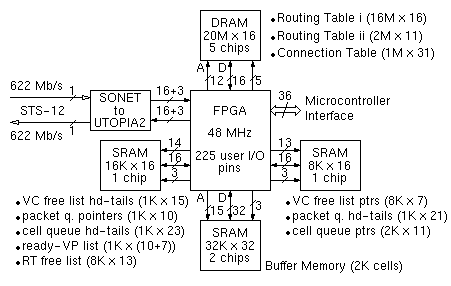
Figure 28:
Block diagram of 622 Mbps wormhole routing filter with buffer
The data structures that are necessary in order to manage the buffered cells, along with the RT free list and VC free list that were also present in figure 26, are maintained in two additional SRAM chips; these need to be separate in order to provide enough parallelism. The additional data structures, in figure 28, are: (i) the packet queues: there can be at most 1024 of them, one per VPout, and at most 1024 buffered IP packets can be kept track of in them; (ii) the cell queues: there can be at most 1024 of them, one per buffered IP packet, and they keep track of the buffered cells (up to 2K); and (iii) the circular list of ready VP's. Because of the 3 additional SRAM chips, the FPGA now needs 225 user I/O pins versus only 140 I/O pins in figure 26.
Figure 29 shows the timing diagrams for the memory accesses during the various operations. We now need 33 clock cycles per cell-time, leading to a requirement for 21 ns clock period, or 48 MHz clock frequency; upper-end, modern FPGA's can reach these requirements. As in section 4.1, we assumed 6 clock cycles (only 125 ns, now) per DRAM access, 3 cycles per SRAM read, and 2 cycles per SRAM write (however, accesses to the buffer memory are sequential, and are thus assumed to proceed at the rate of 1 per clock cycle). If an ASIC is used in place of the FPGA, some or all of the SRAM's can be placed on-chip, thus saving on pins and clock cycles.
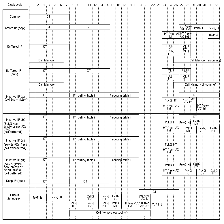
Figure 29:
Memory access timing for the wormhole routing filter with buffer
Overall, we see that a routing filter with buffer is appreciably more complex than a bufferless one. In terms of component cost, we need an FPGA with 60% more pins; we also need 30% more memory chips. Although these may not be too significant, the considerably higher design complexity of a filter with buffer must also be taken into consideration. In conclusion, we see no serious reason for going to a filter with buffer, unless one wants to support packet reassembly at ``exit points'', in which case large buffer space is needed (section 3.3).
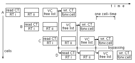
Figure 30: Example of pipelined operation
of a bufferless wormhole routing filter
Once the IP Routing Table (RT) is made to have enough throughput, using techniques such as the above, the operations of the routing filter can be arranged in a pipeline. Figure 30 shows an example of such a pipeline, where each stage corresponds to one cell time (170 or 42 ns). In this example, RT accesses take up to two stages. The Routing Table is read in parallel with the Connection Table (CT): we always and ``blindly'' start a routing look-up before knowing if the current cell is a head cell; if it is not, just throw away the result of the look-up. In the third stage, if the CT indicated a head cell, we get a free VC in the VPout chosen by the RT. The cell is forwarded out in the fourth pipeline stage; if this was a head cell, the CT is updated with the new VP/VC pair. As in most pipelines, there are dependencies among the multiple cells that are being processed in parallel, in the various pipe stages; these dependencies, however, can be resolved using bypassing --a technique commonly used in all processor designs today. As shown in figure 30, the CT entry for cell D is read before cells A, B, and C have had the chance to update the CT --something they should normally have been allowed to do. If cell D belongs to the same VP/VCin as cell C, or B, or A, and if that earlier cell was a head cell that selects a new VP/VCout in its third stage, then cell D must use that VP/VCout; this information is readily available in the latter stages of the pipeline, and can be bypassed (forwarded) to the earlier stage where cell D is being processed, as indicated by the arrows in figure 30. Microprocessors with pipeline cycles under 10 nanoseconds are routinely designed today; it follows that wormhole IP over ATM operation at OC-192 rates (10 Gigabits per second) poses no serious problem with its 42 ns pipeline stage.
As we see, wormhole IP routing filters with ATM switching networks are equivalent to conventional IP routers. Furthermore, the routing function for IP packets is carried out completely in hardware, in this wormhole IP over ATM system. Switching in the ATM (sub-) networks (figure 2) is performed in hardware, according to (permanent) VP's that have been set up (in software) ahead of time. The wormhole routing filters operate in hardware (section 4); their hardest function, routing lookup, is performed e.g. as in [GuLK98], within a delay of two DRAM accesses. Wormhole routing filters have a low delay (one or a few cell times), and can operate at multi-gigabit/second rates (section 4.3). The ATM architecture is also appropriate for building low latency and high throughput switching networks (see e.g. [KaSS97]). It follows that the wormhole IP over ATM architecture is an effective technique for building multi-gigabit-per-second IP routers that handle packets entirely in hardware; only set-up functions are performed in software, off-line: route selection (VP set-up), and routing table set-up.
Wormhole IP over ATM is not just ``yet another technique'' to build gigabit IP routers. Wormhole IP has a number of advantages, stemming from the very essence of its architecture. First, it allows the integration of IP and native ATM traffic, with both of them sharing the same transportation infrastructure, so that capacity left unused by one of them is exploited by the other. Quality of service (QoS) guarantees can be provided to native ATM traffic as usual, leaving such traffic unaffected by the added presence of IP packets. The road is also opened for IP to find new methods to take advantage of ATM's capabilities for QoS guarantees.
The second fundamental advantage of wormhole IP is that it avoids the reassembly delay at all intermediate routing nodes (all routing filters that are between ATM subnetworks). Packet reassembly delay can be very long (figures 22, 23), so avoiding it is important. In essence, wormhole IP performs cut-through routing, at the ATM cell level. One can argue that reassembly delay is long because of the spreading that the previous ATM subnetwork has caused (section 2.3); if all bits of each IP packet were forwarded contiguously in time, as in conventional IP routing, there would be no spreading, no reassembly delay, and cut-through would be less important. While this is true, remember that spreading is desirable so as to allow high priority traffic to interrupt long packet transmissions; this is precisely the method in which the network can offer QoS guarantees regarding delay. Also remember that the segmentation of variable-size packets into fixed-size units, and the independent switching of these units is the key technique used in building gigabit switches and routers.
While wormhole IP is a method to make IP routers that operate entirely in hardware at high speed, many other techniques have been proposed and used for routing IP over ATM. One group of such techniques is LAN emulation, classical IP over ATM, address resolution (NARP), next hop resolution (NHRP), and multiprotocol over ATM (MPOA). These techniques generally suffer from non-scalability when shared servers have to be used, and from connection set-up delays to send IP packets, since conventional ATM signaling is used. Another group is IP switching [NeML98] and its similar techniques, like IP/ATM, cell switch router (CSR), and ipsofacto. These techniques recognize flows, i.e. a sequence of packets with some common characteristics --primarily: destined to the same host. A flow is recognized after a (small) number of packets belonging to it have passed by. After recognition of a flow, an ATM connection is opened for that flow. Setting up such connections is performed using protocols faster than conventional ATM signaling, but still in software. Wormhole IP over ATM is faster than these methods, because it switches all packets --not just packets after their flow has been recognized-- and because connections are set up in hardware, with negligible delay. This increased speed of wormhole IP does not require more expensive hardware. Finally, tag switching [RFC2105] and the similar ARIS proposal set up connections through an ATM (sub-) network ahead of time, and insert these into the IP routing tables, so that when IP packets arrive they can be forwarded immediately over these ready connections. This is similar to what wormhole IP does in the ATM subnetworks of figure 2. If the subnetworks over which connections have been pre-established are the same in tag switching and in wormhole IP, then the two techniques become comparable. In this case, wormhole IP introduces a new method for packets to be routed from one subnetwork to the other, in hardware, without packet reassembly and segmentation, hence with negligible delay. On the other hand, if tag switching tries to pre-establish connections end-to-end across a large ATM network, too many connections (labels) will be needed; if this results in preferentially pre-establishing some but not all connections, packets traveling on non-pre-established routes will suffer.
In conclusion, wormhole IP over ATM applies techniques from multiprocessor interconnection networks to making IP run over existing and future fast ATM equipment, at correspondingly high speed. Switching hardware prefers small, fixed-size traffic units. To be routed at high speed, IP packets are segmented into such fixed-size units (ATM cells). Once such a segmented packet enters the ATM world, it can be routed, according to its IP destination address, from subnetwork to subnetwork, fully in hardware, without intermediate reassembly, with negligible delays. This wormhole cell forwarding, from subnetwork to subnetwork, is performed by the routing filters proposed in this paper.
The wormhole IP routing filter that we proposed and analyzed has a number of advantages: (i) it works together with standard, existing ATM equipment; (ii) it allows the co-existence and integration of both IP and native ATM traffic in the same networks; (iii) the quality of service of native ATM traffic can stay unaffected by the added IP traffic, while IP can benefit from ATM's QoS capabilities; (iv) for IP traffic, the system operates equivalently to a network of low-latency gigabit IP routers. All these come at the modest cost of about 10 off-the-shelf chips per routing filter for 622 Mb/s operation; higher speed operation is feasible, even at 10 Gb/s, today. One factor contributing to simplicity is that, as we showed by simulation based on actual IP traces, a few tens of hardware-managed VC's per outgoing VP are sufficient; the bufferless organization is simpler, and performs very well.
[Barn97] R. Barnett (rbarn@westell.com): ``Connectionless ATM'', IEE Electronics & Communications Engineering Journal, Great Britain, October 1997, pp. 221-230.
[Bork90] S. Borkar e.a.: ``Supporting Systolic and Memory Communication in iWarp'', Proc. of the 17th Int. Symp. on Computer Architecture, ACM SIGARCH vol. 18, no. 2, June 1990, pp. 70-81.
[BCDP97] A. Brodnik, S. Carlsson, M. Degermark, S. Pink: ``Small Forwarding Tables for Fast Routing Lookups'', Proceedings of the ACM SIGCOMM'97 Conference, Cannes, France, Sept. 1997, pp. 3-14.
[DaSe87] W. Dally, C. Seitz: ``Deadlock-Free Message Routing in Multiprocessor Interconnection Networks'', IEEE Trans. on Computers, vol. C-36, no. 5, May 1987, pp. 547-553.
[Dally92] W. Dally: ``Virtual-Channel Flow Control'', IEEE Tran. on Parallel and Distributed Systems, vol. 3, no. 2, March 1992, pp. 194-205.
[Gall97] M. Galles: ``Spider: A High-Speed Network Interconnect'', IEEE Micro, vol. 17, no. 1, Jan./Feb. 1997, pp. 34-39.
[GuLK98] P. Gupta, S. Lin, N. McKeown: ``Routing Lookups in Hardware at Memory Access Speeds'', Proceedings of IEEE Infocom, San Francisco, CA USA, April 1998; http://tiny-tera.stanford.edu/~nickm/papers/ Infocom98_lookup.ps or Infocom98_lookup.pdf
[HaSt98] A. Hatzistamatiou, G. Stamoulis; personal communication, CS-534 course, University of Crete at Heraklion, Spring 1998.
[KaSS97] M. Katevenis, D. Serpanos, E. Spyridakis: ``Switching Fabrics with Internal Backpressure using the ATLAS I Single-Chip ATM Switch'', Proceedings of the GLOBECOM'97 Conference, Phoenix, AZ USA, Nov. 1997, pp. 242-246; http://archvlsi.ics.forth.gr/atlasI/atlasI_globecom97.ps.gz
[LeBo92] J. LeBoudec: ``The Asynchronous Transfer Mode: A Tutorial'', Computer Networks and ISDN Systems, vol. 24, no. 4, May 1992.
[NeML98] P. Newman, G. Minshall, T. Lyon: ``IP Switching: ATM Under IP'', IEEE/ACM Transactions on Networking, vol. 6, no. 2, April 1998, pp. 117-129; http://www.ipsilon.com/~pn/papers/ ton97.ps or ton97.pdf
[NLANR97] USA National Laboratory for Applied Network Research (NLANR) (http://www.nlanr.net): IP traffic trace from FIXWEST West Coast federal interexchange node of January 1997, available at: ftp://oceana.nlanr.net/Traces/FR+/9701/
[RFC2105] Y. Rekhter, B. Davie, D. Katz, E. Rosen, G. Swallow: ``Cisco Systems' Tag Switching Architecture Overview'', IETF RFC2105, Feb. 1997; http://info.internet.isi.edu:80/in-notes/rfc/files/rfc2105.txt
[WVTP97] M. Waldvogel, G. Varghese, J.Turner, B. Plattner: ``Scalable High-Speed IP Routing Lookups'', Proceedings of the ACM SIGCOMM'97 Conference, Cannes, France, Sept. 1997, pp. 25-36.