
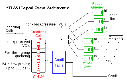
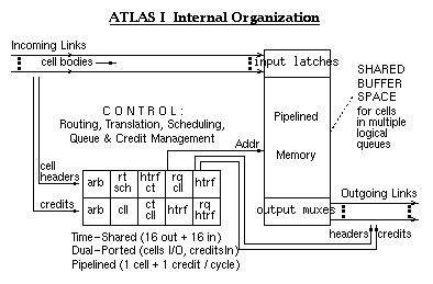
The ATM cells themselves are stored in the (single) shared cell buffer, and are never moved until they depart. Pointers to the cells are placed in various logical queues. The Ready Queues contain pointers to the cells that are ready for departure; they are organized per-output and per-priority level (service class). Three separate ready queues, not shown in the figure, exist for multicast cells, one multicast queue per priority level. "Backpressured VC's" are the connections that are subject to credit-based flow control. Backpressured VC cells are first logically placed in the Creditless Cell List; then, when they acquire the credit(s) that are necessary for their transmission, they are logically moved to the proper Ready Queue.
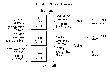
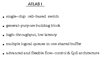
ATLAS I follows the philosophy that hardware ought to provide mechanisms , leaving it to users to implement the policies that they like, in software, using appropriate combinations of hardware mechanisms. Thus, ATLAS I provides three priority levels. The scheduler of each output link first empties the corresponding high-priority ready queue; when that queue is empty, cells are forwarded from the middle-priority ready queue; the low-priority queue is only serviced when both of the above are empty. Backpressure is (optionally) provided for the connections belonging to the two lower classes. It is expected that the upper two class connections are policed at their sources. The three classes provided represent the useful combinations of the two parameters: source policing, and backpressure. A fourth, non-policed, non-backpressured class would make no sense: almost all of its cells would be dropped, because the non-policed class-3 connections will normally flood the network, absorbing any available link capacity that remains unused by the two upper class connections.
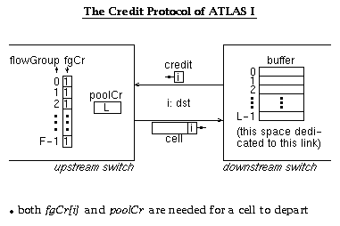
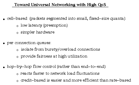
The credit flow control protocol of ATLAS I is similar to QFC, but is adapted to hardware implementation over short and reliable links. For each link, the downstream switch allocates a buffer pool of size L. The upstream switch maintains a pool credit count per output, corresponding to the available space in that pool. Separate credit counts, fgCr, are maintained for each flow group. For a cell to depart, both kinds of credit are needed. Credits operate on the granularity of flow groups, because it may be undesirable or infeasible for them to operate on individual connections when the number of such connections is too large. A flow group is a set of connections over a common path through the network; their cells never overtake each other. ATLAS I links can carry up to 4096 flow groups, each; the chip can merge multiple incoming flow groups into each outgoing flow group.
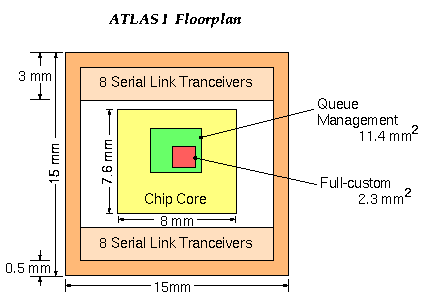
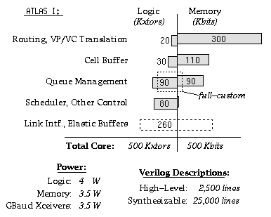
The pad ring and the 16 Serial Link Transceivers are provided by BULL, France. The core is designed by FORTH, Crete, Greece.
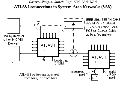
ATLAS I chips can be connected directly to each other and to other HIC/HS devices. ATLAS I chips can be managed locally, by a microprocessor attached to the switch, or remotely, via normal network links. In case of remote management, an (inexpensive) serial ROM attached to each ATLAS I chip takes care of bootstrapping; it initializes the translation table so that cells arriving on a given VC of a trusted link are routed to the internal management command circuits.
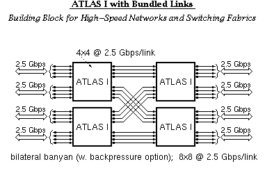
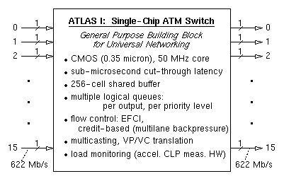
ATLAS I links can be bundled together, in groups of 2, behaving like a 1.24 Gb/s link, or in groups of 4, providing the equivalent of 2.5 Gb/s links, or in groups of 8, giving 5.0 Gbps/link.
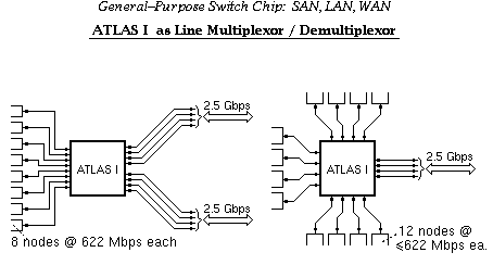
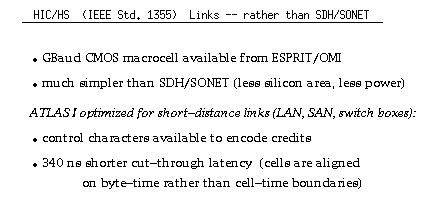
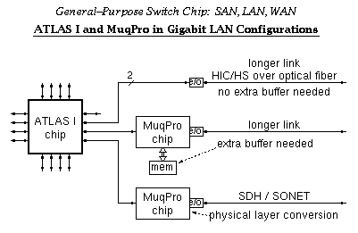
For longer distance connections, plain electro-optical converters and an optical fiber suffice when no extra buffer space is needed. For additional, off-chip buffer space, and/or for physical layer conversion, a second chip, called MuqPro (Multiqueue Processor), is foreseen. ATLAS and MuqPro form a two chip set of building blocks for universal networking. MuqPro contains those functions that are only needed when connecting to a remote site; by placing these functions outside ATLAS I, their cost need only be paid when actually necessary. Design and fabrication of the MuqPro, in single-chip form, is outside the scope of the current ASICCOM Project; however, several subsets of MuqPro's functionality are included in the various board-level and FPGA-based subsystems that the ASICCOM partners are building for the ASICCOM demonstration system.
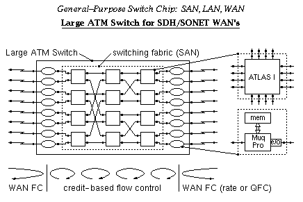
An ATM switch box, with a large fan-in and fan-out, can be made out of ATLAS I chips, interconnected to form a switching fabric (a System Area Network - SAN), and MuqPro interfaces to the external links; large buffer memory is provided by off-chip DRAM connected to the MuqPro chips. In such a configuration, backpressure (credit-based flow control) is advantageously used inside the switching fabric, to provide the high performance of output queueing at the low cost of input buffering, as explained below. MuqPro's interface this internal backpressure to whatever external flow control method is chosen (e.g. rate-based of credit based). For rate-based flow control over the WAN links, the size of queue number j in MuqPro chip number i indicates whether the connections going from port i to port j currently exceed their fair share of throughput or not (see below for explanation).
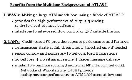
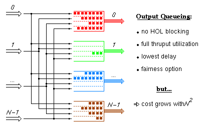
Output queueing is the ideal switch architecture from the point of view of performance, but it becomes impractical for large valency switches because its cost grows with the square of the number of links. Below we will see how ATLAS I based switching fabrics with internal backpressure emulate this architecture so as to provide comparatively high performance at a significantly lower cost. In this and the next two trancparencies, the color of a cell indicates the output port of the fabric that this cell is destined to (in the ATLAS I based fabric, this will identify the flow group that the cell belongs to).
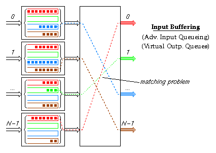
Input buffering (otherwise called advanced input queueing, or virtual output queues at the inputs) is one method by which designers have tried to provide high switch performance at reasonable cost. It avoids the head-of-line blocking problem of FIFO input queueing by providing multiple logical queues (one per output) in each input buffer. The switch part of this architecture must solve a matching problem during each cell time: for each input buffer, choose one of the cell colors present in it, so that no two input buffers have the same color chosen, and so that the number of colors chosen is maximized (or other performance criteria, e.g. fairness). For large valency switches, this matching problem is extremely hard to solve quickly and with good performance. Bellow we will see how ATLAS I based switching fabrics with internal backpressure emulate the solution of this matching problem in a progressive and distributed manner.
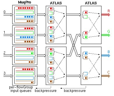
The effect of the ATLAS backpressure is to push most of the output queue cells back near the input ports. The head cells of the output queues, however, are still close to their respective output ports. The fabric operates like an input-buffered switch where the ATLAS chips implement the arbitration and scheduling function in a distributed, pipelined fashion. In every link, all connections going to a given output port of the fabric form one flow group (colors correspond to flow groups). Each MuqPro maintains separate logical queues for each flow group. For simplicity, this transparency only shows a 4x4 fabric made of 2x2 switch elements --this architecture, however, scales perfectly well to very large switching fabrics. In this switching fabric, the only external memories are those attached to the MuqPro's, whose cost is the same as in input buffering. In order for the cost to be kept at that low level, the building blocks of the switching fabric (i.e. ATLAS) must not use off-chip buffer memory. Since buffer memory in the switching elements has to be restricted to what fits on a single chip, backpressure is the method to keep this small memory from overflowing all the time. Performance-wise, this switching fabric offers properties comparable to those of output queueing. Saturation throughput is close to 1.0 even with few lanes (see below). No cell loss occurs in the fabric --cells are only dropped when the (large) MuqPro queues fill-up. Traffic to lightly loaded destination ports (e.g. G) is isolated from hot-spot outputs (e.g. R) as verified by simulation (see below).
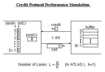
We simulated Banyan networks like the ATLAS-MuqPro backpressured fabric above. Flow groups corresponded to destinations. The switch elements simulated were implementing a credit flow control protocol that is a generalization of the ATLAS I protocol: the flowGroup (destination) credits were initialized to any number --not just 1, as in ATLAS I.
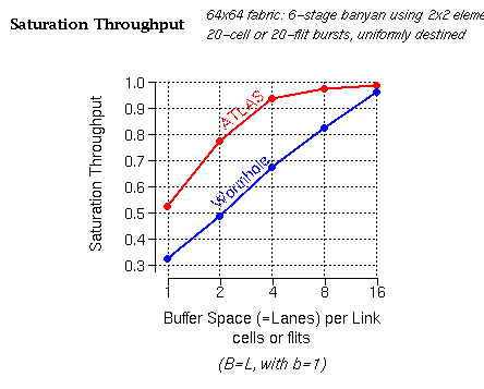
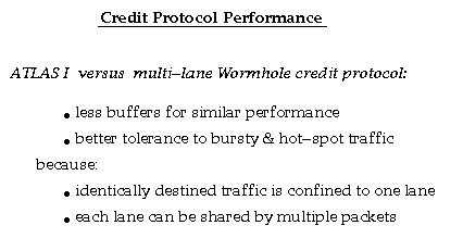
We see that a modest buffer space --around 8 to 16 cells per incoming link (for the low priority class)-- suffices for the outgoing links to reach full utilization (presumably, by low priority traffic, which fills in whatever capacity remains unused by higher priority traffic). The ATLAS protocol (red line) performs better than the traditional multilane wormhole protocol for the reasons outlined below.
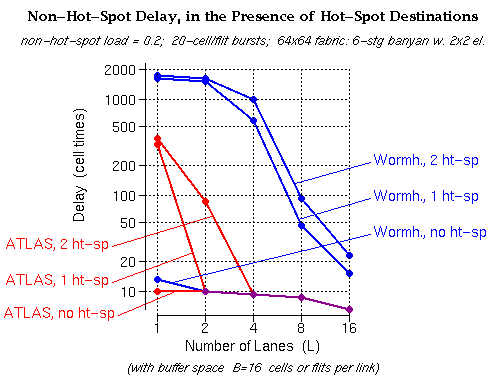
With the ATLAS protocol, when the number of lanes is larger than the number of hot-spot output ports of the fabric (1 or 2 ports --upper two red curves), the delay to the non-hot-spot outputs remains unaffected by the presence of hot-spots (it is the same as when there are no hot-spot outputs --bottom red curve). This is precisely the ideal desired behavior for hot-spot tolerance.
